Phone:86-0714-3056766 E-mail:sukie@hbzpdz.com
Material of rigid and flex board
The PCB design trend is toward the light and small direction. In addition to high density PCB design. There are also such important and complex field for three-dimensional connection assembly of rigid and flex board. With the generate and development of FPC. The new product of rigid and flexible combination is gradually widely used in various occasions. The flexible circuit board and traditional rigid circuit board after many processes, according to the relevant process requirements combined together. Then formed the rigid and flex board at the same time. It can be used in some products with special requirements, including some flexible areas and also some rigid areas. It is great help for save the internal space of production and reduce the volume of finished production. It is also may help for improve the performance of production.LED PCB board
MATERIALS FOR RIGID AND FLEX BOARD
When considering the design and production process of rigid and flex board. It is very important to be well prepared.However,it requires professional knowledge and understanding of the material characteristics. The material selected for the rigid and flex board will directly affect the subsequent production process and performance.
We are all familiar with hard board material. We usually use FR4 type material. But there are a number of requirements that need to be considered the rigid material used for rigid and flex board. It needs to be suitable for adhesion and heat resistance. To ensure that rigid flexural joint no deformation after heat expansion. General manufacturer used resin series of rigid material.
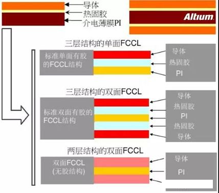
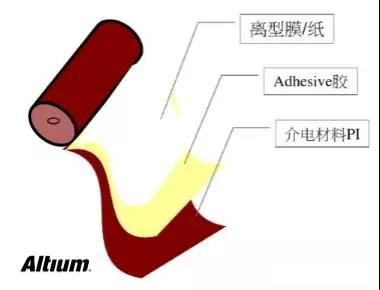
For flex board material. We choose the base material and coverlay with smaller expansion and contraction. It generally using harder PI materials. Partly direct use of non - adhesive material for production. Flex board material is shown as follows:LED PCB board
PI.Polymide:Kapton(12.5um/20um/25um/50um/75um)。
Good flexibility, high temperature resistance (260°C in long term, 400°C in short term), high moisture absorption, good electrical and mechanical properties, good tear resistance, good weather resistance and chemical resistance, high flammability. PI are the most widely used. 80% of them are made by DuPont, USA.

PET. Polyester(25um/50um/75um) Low-cost, flexible, tear resistance. Good mechanical and electrical properties. Good water resistance and moisture absorption. But it is easy to shrink after heat. It isn’t fit for high temperature resistance. Not suitable for high temperature tin welding. The melting point is 250°C. It is less used.
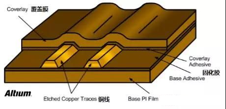
Coverlay
The main function of the coverlay is to protect the circuit from moisture, pollution and welding.
The thickness is from 0.5mil to 5mil (12.7 to 127um)
Conductive Layer
The conductive layer can be divided into Rolled Annealed Copper, Electrodeposited Copper and silver sputtering silver ink. The crystal structure of electrolytic copper is rough, which is not conducive to product fine line. The crystal structure of Rolled Annealed Copper is smooth, but it has poor adhesion to the base film. It can distinguish from the appearance between Rolled Annealed Copper and Electrodeposited Copper. Electrodeposited Copper is red. But Rolled Annealed Copper is gray.
Additional Material & Stiffeners
Rigid material is pressed on the local area of the flex board for welding components or adding reinforcement for installation. Stiffeners can be used FR4, resin board, pressure sensitive adhesive, steel sheet , aluminum sheet and so on.
Low Flow PP
It is used for rigid and flex connection. The PP is usually very thin. The general has 106(2mil),1080(3mil/3.5mil),2116(5.6mil) these specifications.
Structural style for rigid and flex board

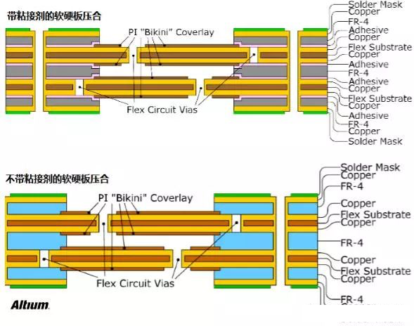
There is one or more rigid layers glued to the flexible board in stack-up. The circuits on the rigid and flexible layers are metallized into each other. Each rigid and flexible board has one or more rigid zones and flexible zone. The combination of simple rigid and flexible board as shown below.
In addition, the combination of flexible board and rigid board use of drilling plated holes, lamination technology to achieve electrical connection. LED PCB boardAccording to the design requirements, the design concept is more suitable for installation and debugging of devices and welding operations. To ensure better use of the advantages and flexibility of rigid and flexible board. This is a complicated situation. With more than two layers of circuit. As follows:

Lamination is the combination of copper foil, PP, inner flexible circuit and outer rigid circuit. The lamination of rigid and flexible board is different from that of purely flexible or rigid board. The deformation of flexible area in laminating process and the surface flatness of rigid plates should be considered. LED PCB boardTherefore, in addition to material selection, the thickness of the rigid board should be considered in the design process. To ensure that the expansion and contraction rate of the rigid part are consistent. Then it is without warping. 0.8mm-1.0mm thickness is more suitable by experiment proved. At the same time, it should be noted that the via need to be placed at safe distance from the joint between flexible and rigid area. So it doesn’t affect the area of rigid and flexible combination. L
